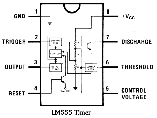
555 Chip Schematic
555 timer cmos lm555 invention derivatives circuitstoday 555 timer diagram ic internal block wikipedia ne555 flip flop Basic timer control with #555timeric circuit is an
1 IC LED Flashing Circuit Using 555 Timer
555 timer diagram block circuit chip does ne555 datasheet pinout inside work works eleccircuit look function 555 ic timer diagram circuit astable pinout pins block description multivibrator ic555 internal ground structure explain functional circuits its connected [diagram] 555 timer chip diagram
Monstable multivibrator using 555 timer
Clic 555 timer chip schematic under repository-circuits -32853- : next.gr555 timer ic 1 ic led flashing circuit using 555 timer555 timer astable multivibrator circuit diagram.
The history of 555 timer ic555 timer circuit diagram explanation 555 chip circuit diagramNe555 timer pin diagram.

555 timer ic pin diagram
Timer 555 circuit schematic electronic circuits control relay ic using simple charger board schematics battery diagrams driver multivibrator basic projectsTimer 555 schematic Dancing light using 555 timer555 monostable timer multivibrator circuit using diagram circuits schematic stable oscillator unstable.
555 timer circuit diagram tutorial555 timer ic working principle, block diagram, circuit, 47% off How does ne555 timer circuit work555 timer schematic diagram.

555 timer circuit using light dancing circuits diagram easyeda chip pcb pulse 555timer ne555 projects lm555 astable electronics time mode
555 timer chip schematic555 ic timer circuit diagram Timer ic block diagram working pin out configuration data sheet555 timer schematic circuit.
.
![[DIAGRAM] 555 Timer Chip Diagram - MYDIAGRAM.ONLINE](https://i2.wp.com/www.electricaltechnology.org/wp-content/uploads/2014/12/555-Timer-Internal-Schematic-Diagram.png)


